| I. |
Introduction |
| |
The model 600 estate mighty spreader is designed primarily for the horseman, small farmer, or homesteader with a need for spreading manure with a small horsepower tractor. It can be pulled directly into small places, yet has a capacity large enough to minimize the number of loads. Straw, hay or manure of most consistencies can be spread with ease. Strict adherence to maintenance is necessary to insure long life and continued operation.
CAUTION: the spreader should only be operated when all surroundings are clear of people and breakable objects to prevent possible injury or damage. |
| II. |
Assembly Instructions |
| |
 |
| |
Tools required:
a. 1/2 inch wrench (open or box end)
b. 7/16 inch wrench (open or box end)
c. 3/4 inch opened end wrench
d. Hammer
e. Pliers
f. 3/16" allen wrench
g. 3/32" allen wrench
h. Grease gun
i. Wood block
|
:::::::::::::::::::::::::::::::::::::::::::::::::::::::::::::::::: PAGE BREAK ::::::::::::::::::::::::::::::::::::::::::::::::::::::::::::::::::
Assembly Instructions (cont'd)
| 1. |
Install wheels by inserting four lug bolts into each hub so that threads protrude out. Install hub onto axle and insert 1/4" x 1 3/4" bolt and lock nut through hub and axle hole provided. Slide the wheels onto the hub bolts with the valve stem facing outward. Install lug nuts and tighten securely. |
| 2. |
Assemble the front slant panel by bolting the three predrilled short boards to the left and right supports using the six 1/4" carriage bolts and nuts. (The short side of each slant panel support faces inward) set the front slant panel onto the spreader so the mounting holes align with the side rail mounting holes. Loosely install 5/16" x 1" bolts and nuts into front mounting holes to hold panels in place for step 3. |
| 3. |
Install tongue over slant panel rear mounting holes and insert 5/16" x 1" bolts and nuts through rear mounting holes of tongue, slant panel, and side rails. Remove slant panel front mounting bolts installed in step 2 above. Swing tongue upward until front mounting holes align. Reinsert bolts and nuts, tighten all four mounting bolts. |
| 4. |
Slide beater ends into the two bearings located on the two support brackets and install beater assembly at the rear of the spreader using four 5/16" x 1" bolts and nuts. Insure that the beater supports are firmly against the bottom of the side rail before tightening. The bolts should be inserted so that the bolt heads are on the outside to prevent interference with the other components. The mounting holes are slotted for beater and drag chain paddles during operation. |
| 5. |
Install rear stabilizer bar into square tube on each beater support bracket. Slight hammer tapping might be necessary using a wood block between hammer and bar. Insure that the bar is not cocked to preclude binding of beater during operation. |
| |
Note: make sure beater turns freely. If not, loosen beater bearing bolts and retighten |
| 6. |
Install sideboards into slots provided by front slant panel and rear beater supports. Insert angle iron side stakes to provide outward support of the sideboards. |
| 7. |
Install beater drive pulley onto beater shaft using the 5/8" long key way insert and tighten allen screw on pulley. Install beater drive v-belt with tightener arm positioned on the topside of the v-belt. The tightener arm is spring loaded from the opposite side of the spreader. When the clutch lever is pulled forward, the tightener arm should clear the v-belt. At this point tighten the allen screw on the 1/4" shaft collar so that the clutch lever is held forward via the set collar and keyhole located forward of the clutch lever. |
| 8. |
Grease the two wheel bearings at the fittings located on the two axle supports. Grease the beater drive pulley bearing located behind the 8 inch pulley on the side rails of the chassis. |
:::::::::::::::::::::::::::::::::::::::::::::::::::::::::::::::::: PAGE BREAK ::::::::::::::::::::::::::::::::::::::::::::::::::::::::::::::::::
| III. |
Operating Instructions
The basic operation of the estate mighty spreader is identical to full farm sized spreaders. The entire manure load is gradually fed toward the rear beater at a rate compatible with the rear beater's ability to disperse the manure. The rear beater final drive is a v-belt to allow slippage should excessive chunks be encountered; thus preventing severe damage to more expensive components.
Movement of the drag chain is accomplished in small increments using the right wheel as a driving force to cause a reciprocating motion of the ratchet mechanism. Two drag chain speeds are available as described under section IV.
The rear beater rotation is driven by the left axle wheel force through a combination link chain, spur gear, and pulley arrangement. The drag chain and rear beater have separate clutch levers, both of which are located at the rear of the spreader. Detailed operating procedures are as follows:
| 1. |
Insure that the drag chain tension is such that a small sag (2-3 inches) is apparent underneath the front of the load bed. Drag chain tension is adjusted by using the two idler sprocket positioning bolts located at the front inside of the load bed. (Just inside the tongue mounting bolts.) |
| 2. |
Disengage the drag chain clutch by rotating the spring loaded lever on the ratchet gear located at the right rear of the load bed. |
| 3. |
Disengage the rear beater clutch by pulling the spring loaded handle forward until the 1/4" holding set collar is through its latch hole located just in front of the clutch handle. The set collar will hold the lever forward until manually released. |
| 4. |
Load desired material to be spread. Caution: avoid loading rocks, metal or other items that could become dangerous flying objects during unloading. Also, string and wire should be avoided to prevent its winding on the beater while unloading. |
| |
Small loads are recommended until familiarization with limitations and capabilities of the model 600 are satisfactory. Note: if sawdust bedding is used, it may be desirable to place a burlap sack or other suitable material at the rear of the spreader in such a manner as to keep manure from pouring out the rear beater opening while loading. The bag is easily removed before spreading. Or, a rear door can be installed simply by forming a groove at the rear of the load bed with narrow boards attached vertically. A piece of plywood will slide in and out easily before loading and spreading. |
| 5. |
Upon reaching the desired location of spreading, engage the two clutches in a reverse manner of step 3 above. |
| 6. |
Two drag chain speeds are available. See section IV adjustment. |
| 7. |
The spreader works most efficiently when being pulled at speeds of 3-5 miles per hour (fast walk). If the beater stops rotating during dumping operations, the driver should stop immediately and manually rotate the beater until free. This will prevent the manure from becoming further jammed into the beater. Also, when turning corners while spreading, it is better to make left hand turns so the beater speeds and spreading action are maintained. |
|
:::::::::::::::::::::::::::::::::::::::::::::::::::::::::::::::::: PAGE BREAK ::::::::::::::::::::::::::::::::::::::::::::::::::::::::::::::::::
| IV. |
Adjustment Points
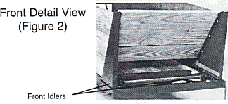
| 1. |
Drag chain-adjustments is provided on the front idler sprockets by using a 3/4" wrench. Do not over tighten the drag chain. Allow a 2-4 inch sag on chain (see figure 1 and 2). |
|
|
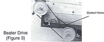
| 2. |
Beater drive chain - the beater is driven via the left wheel with the power being transmitted through a chain, transmission gears, and a v-belt. The chain will eventually stretch. Slotted holes within the transmission provide the tightening capability. (See fig. 3). |
| 3. |
Beater/drag chain clearance - the beater can be raised or lowered via the slotted holes at the beater bearing mounting. Maintain at least 1/4" clearance. |
 |
|
| V. |
Maintenance
| 1. |
Before heavy usage, grease the unit thoroughly at the 8" pulley bearing and two wheel bearings. Additionally grease or heavy oil should be regularly applied at all other moving joints. |
| 2. |
After each usage, clean excessive build up of material in cracks and corners of the unit. The effort will prolong the life of the spreader, helping to prevent corrosion. |
| 3. |
Periodically tighten all nuts and bolts to eliminate elongation of the holes and potential failure of components. |
| 4. |
Maintain an obvious sag (2-4 inches) in the drag chain. Too much tension will cause excessive loads on all components. |
| 5. |
Maintain proper tire inflation pressure according to marking on tires. |
| 6. |
Periodically check v-belt for excessive slack. |
| 7. |
See section IV for various adjustment points. |
|
:::::::::::::::::::::::::::::::::::::::::::::::::::::::::::::::::: PAGE BREAK ::::::::::::::::::::::::::::::::::::::::::::::::::::::::::::::::::

:::::::::::::::::::::::::::::::::::::::::::::::::::::::::::::::::: PAGE BREAK ::::::::::::::::::::::::::::::::::::::::::::::::::::::::::::::::::
| Item No. |
Description |
Part No. |
Qty |
 |
| 1 |
MAIN SUPPORT FRAME |
6001 |
1 |
| 2 |
16.00 x 6.50 - 8 WHEEL/TIRE ASSEMBLY |
6002 |
2 |
| 3 |
1/4" x 1 3/4" GRADE 5 BOLT/NUT |
-- |
5 |
| 4 |
3/4" FLAT WASHER |
-- |
1 |
| 5 |
3/4" I.D. SLEEVE BEARING |
6003 |
4 |
| 6 |
CAM SHAFT |
6004 |
1 |
| 7 |
1/8" COTTER PIN |
-- |
2 |
| 8 |
DRIVE SPROCKET |
6005 |
3 |
| 9 |
DRIVE CHAIN (#55 LINK CHAIN) |
6006 |
1 |
| 10 |
3/4" BEATER DRIVE AXLE |
6007 |
1 |
| 11A |
TRANSMISSION HOUSING |
6008A |
1 |
| 12 |
5/8" X 3 1/2" GRADE 5 BOLT |
-- |
1 |
| 13 |
5/8" NUT |
-- |
1 |
| 14A |
COMBINATION SPROCKET ASSEMBLY |
6009A |
1 |
| 16 |
5/16" X 1" GRADE 5 BOLT/BUT/WASHER ASSEMBLY |
-- |
16 |
| 17 |
DRIVE PULLEY (8 X 5/8" BORE) |
6011 |
1 |
| 18 |
BELT TIGHTENER ROD |
6012 |
1 |
| 19 |
1" X 6" WOLMANIZED SIDE BOARD |
6013 |
6 |
| 20 |
SIDE BOARD SUPPORT STAKE |
6014 |
2 |
| 21 |
4L690 V-BELT (69") |
6015 |
1 |
| 22 |
BEATER SHAFT PULLEY (8 X 3/4" BORE) |
6016 |
1 |
| 23 |
BEATER STABILIZER BAR |
6017 |
1 |
| 24 |
LEFT BEATER SUPPORT |
6018 |
1 |
| 25 |
RIGHT BEATER SUPPORT |
6019 |
1 |
| 26 |
BEATER ASSEMBLY |
6020 |
1 |
| 27 |
DRAG CHAIN ASSEMBLY (#55 LINK CHAIN) |
6021 |
1 |
| 28 |
BEATER SUPPORT BEARING |
6022 |
2 |
| 30 |
3/32" COTTER PIN |
-- |
2 |
| 31A |
RATCHET FLIPPER |
6024A |
1 |
| 32 |
RATCHET SPRING |
6025 |
1 |
| 33A |
CONNECTOR ROD BOLT/NUT ASSEMBLY |
6026A |
2 |
| 34A |
CONNECTOR ROD |
6027A |
1 |
| 35 |
1/4" FLAT WASHER |
-- |
1 |
| 36 |
BEATER CLUTCH HANDLE |
6028 |
1 |
| 37 |
BEATER CLUTCH SPRING |
6029 |
1 |
| 38 |
5/8" FLAT WASHER |
-- |
2 |
| 39 |
BEATER CLUTCH HOLD ROD |
6030 |
1 |
| 40 |
1/4" SET COLLAR |
6031 |
1 |
| 41 |
IDLER SPROCKET ADJUSTER |
6032 |
2 |
| 42 |
IDLER SPROCKET |
6033 |
2 |
| 43 |
1/2" HEX NUT |
-- |
2 |
| 44 |
1/4" X 1 1/2" CARRIAGE BOLT/NUT/WASHER ASSEMBLY |
-- |
6 |
| 45 |
FRONT SLANT PANEL BOARDS (1" X 6") |
6034 |
3 |
| 46 |
LEFT SLANT PANEL SUPPORT |
6035 |
1 |
| 47 |
RIGHT SLANT PANEL SUPPORT |
6036 |
1 |
| 48 |
IDLER SHAFT |
6037 |
1 |
| 49 |
1" X 6" WOLMANIZED FLOOR BOARD |
6038 |
5 |
| 50 |
FLOOR BOARD HOLD BRACKET |
6039 |
1 |
| 51 |
TONGUE ASSEMBLY |
6040 |
1 |
| 52 |
WHEEL HUB ASSEMBLY (INCLUDES LUG BOLTS/NUTS) |
6041 |
2 |
| 53 |
3/16" X 5/8" KEY WAY INSERT |
6042 |
3 |
| 53A |
3/16" X 1/2" KEY WAY INSERT |
6042A |
1 |
| 54 |
5/8" ID BRONZE BUSHING |
6043 |
2 |
| 55 |
PULLEY DRIVE SHAFT |
6044 |
1 |
| 56 |
3" IDLER PULLEY |
6045 |
1 |
| 57 |
12 TOOTH SPROCKET |
6046 |
1 |
| 58 |
3/8" X 1 1/2" CARRIAGE BOLT/NUT |
6047 |
1 |
| 59 |
#35 TRANSMISSION CHAIN |
6048 |
1 |
| 60 |
DRAG CHAIN DRIVE SHAFT |
6049 |
1 |
| 61 |
RATCHET SPROCKET |
6050 |
1 |
| 62 |
RATCHET DRIVE PLATES |
6051 |
2 |
|
:::::::::::::::::::::::::::::::::::::::::::::::::::::::::::::::::: PAGE BREAK ::::::::::::::::::::::::::::::::::::::::::::::::::::::::::::::::::
WARRANTY POLICY
Country Manufacturing, Inc., will, at its option, replace or repair, without charge to the original purchaser any part or parts manufactured by it and found upon examination, to be DEFECTIVE IN MATERIAL AND/OR WORKMANSHIP if received for such examination within 90 days from date of original purchase.
Damage resulting from accident, abuse or neglect are conditions under which warranty cannot be claimed. Nor will warranty apply to damage resulting from failure to follow the Manufacturer's instruction for operation and maintenance nor from the improper selection of a particular application.
All transportation charges on, and damages and loss incurred in connection with the transportation of, parts submitted for replacement or repair under this WARRANTY shall be borne by the purchaser.
No other warranties, guarantees, or liabilities, either implied or expressed, will be the responsibility of Country Manufacturing, Inc.
:::::::::::::::::::::::::::::::::::::::::::::::::::::::::::::::::: PAGE BREAK ::::::::::::::::::::::::::::::::::::::::::::::::::::::::::::::::::